Next: HydrogeologicMapping Tasks
Up: Hydrogeologic Mapping
Previous: Hydrogeologic Mapping
Subsections
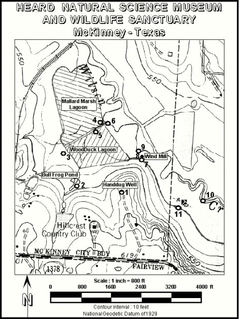
We will make use of a topographic base map (Fig. 6.1) to
map an approximation of the water table at the Heard Museum.
Figure 6.1:
Heard Museum topographic map.
Sample points are labeled by number and name (see Table ![[*]](crossref.gif) ).
).
|
|
In order to do this, we will collect water elevation data, by measuring the
height of surface and groundwater occurrences relative to known
elevation benchmarks. The method is summarized in
Fig. 6.2 and a form for field notes is provided in
Table 6.1. Given these point elevations,
and assuming that the water table roughly parallels the ground
surface, we will construct a contour map of the water table.
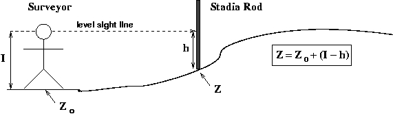
Figure 6.2:
Field procedure for measuring
elevation difference from a known point using a sighting
level. Note our feet will stay dry, so  and therefore
  .
.
|
|
HydrogeologicMapping Leveling Procedure
To carry out a leveling survey (see Fig. 6.2 for
meaning of symbols):
- select an instrument man (person doing the sighting)
- measure eye-height
 using stadia rod held close to the
instrument man
using stadia rod held close to the
instrument man
- instrument man stands on a benchmark (point of known elevation
 )
)
- rod man places base of stadia rod at location where ground
elevation
 is sought
- instrument man reads elevation on stadia rod, holding sight
level so that level bubble is centered on line in viewfinder,
 is the position of the viewfinder line on the stadia rod
- For elevation differences greater than height of rod, or
distances too far to read stadia rod with hand level
- surveyor determines at an intermendiate location
- then moves to that location and repeats these steps as
needed.
- In this case the formula for elevation becomes:
 .
.
- Remember to record and for each of these
``turnaround'' points (see extra lines in Table
6.1)
HydrogeologicMapping Well Measurement Procedure
When wells are available, the water table elevation is measured by
determining the elevation of the ground at the well (``collar
elevation''), and subtracting the depth to water measured by beeper
tape.
- determine the elevation of the ground adjacent to the well ()
- if a well housing is present, measure the height of this (
 )
)
- measure the depth to water from the top of the well housing (
 )
)
- water table elevation
Table 6.1:
Field data form for leveling survey. All values in feet,
water elevation
 .
.
| Station |
Station |
Benchmark |
Eye |
Rod |
Water |
| # |
Name |
Elev () |
Height (I) |
Reading (h) |
Elev. (Z) |
| 1 |
Hand-dug Well |
593 |
|
|
|
| 2 |
Bullfrog Pond |
548 |
|
|
|
| |
|
|
|
|
|
| |
|
|
|
|
|
| |
|
|
|
|
|
| 3 |
Stagnant Pond |
533 |
|
|
|
| |
|
|
|
|
|
| |
|
|
|
|
|
| |
|
|
|
|
|
| 4 |
Mallard Marsh Lagoon |
528 |
|
|
|
| |
|
|
|
|
|
| |
|
|
|
|
|
| |
|
|
|
|
|
| 5 |
Woodduck Lagoon |
528 |
|
|
|
| |
|
|
|
|
|
| |
|
|
|
|
|
| |
|
|
|
|
|
| 6 |
Upper Wilson Creek |
528 |
|
|
|
| |
|
|
|
|
|
| |
|
|
|
|
|
| |
|
|
|
|
|
| |
|
|
|
|
|
| 7 |
Canoe Trail |
525 |
|
|
|
| |
|
|
|
|
|
| |
|
|
|
|
|
| |
|
|
|
|
|
| |
|
|
|
|
|
| 8 |
Windmill |
525 |
|
|
|
| |
|
|
|
|
|
| |
|
|
|
|
|
| 9 |
Lower Wilson Creek |
525 |
|
|
|
| |
|
|
|
|
|
| |
|
|
|
|
|
| |
|
|
|
|
|
| |
|
|
|
|
|
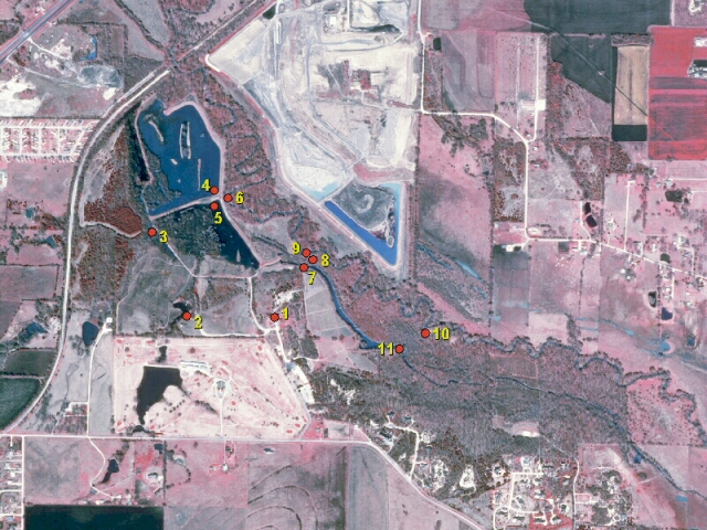
Proceed through the points in numerical order, see Fig. 6.3
for help in navigating the route.
Figure 6.3:
Satellite image of Heard Museum, with sample locations.
Location numbers are upright when photo is oriented with north up.
|
|
- Gather at site of new Science Center (north of Heard Museum
Visitor Center). In the center of the traffic circle is Point 1
(Fig. 6.1).
- Assemble your team and make a site reconnaissance using the
material handed to you
- First observation will be done at the hand-dug well (Point 1,
Fig. 6.1), in the parking lot. Use the Well
Measurement procedure (section 6.1.2).
- Go to next points (2, 3, 4, ...on the map) and evaluate the
surface water level using the hand-leveling technique shown in
Fig. 6.2
- Record all the values in the data table
Table 6.1.
- Measure the groundwater level at the point Wind Mill well
using the beeper tape.
- Determine the elevation of the base of the concrete housing
of the well using the leveling technique
- Determine water table elevation using the Well
Measurement procedure (section 6.1.2)
Next: HydrogeologicMapping Tasks
Up: Hydrogeologic Mapping
Previous: Hydrogeologic Mapping
GEOS 3110 Professor's Notes, Summer 2007
Dr. T. Brikowski, U. Texas-Dallas. All rights reserved.