Design Vision by Synopsys
Properly quit Design Vision
We have limited number of Synopsys licenses. If you fail running Design Vision and reported an error stating all of the licenses are occupied, it means no available license.
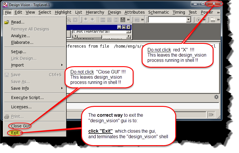
To quit Design Vision, DO NOT simply click on the close button on the top right corner. Instead, you should go to File -> Exit to properly quit Design Vision and release occupied license.
1. Synthesis
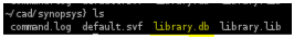
Generate library.db
Start Desgin Vision
Go to your Synopsys working directory first.
cd ~/cad/synopsys
Please source the below profile whenever you are using Synopsys tools
. /proj/cad/startup/profile.synopsys_2018
To run Design Vision, type the following to start Design Vision:
design_vision &
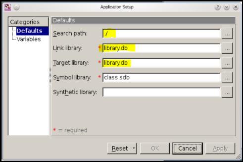
Setup design library by selecting File->Setup. Then click OK.
- Make sure the search path is current directory i.e. "./"
- The name of
link libraryandtarget libraryneed to be "library.db"
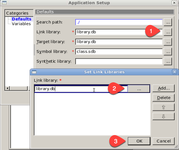
If you store library.db at other location, you can not use default setting, set library location as following.
Read Design
Verilog Design Entry
Open your design by selecting File->Read from the menu bar. In the Read File dialog box, select your verilog file and click OK.
VHDL Design Entry
File -> Analyze and then, click Add, and add your file.
File -> Elaborate and then, click OK.
Note that you have just read in your design, You have not compiled or mapped it into digital gates yet. You need to do that next.
Compile Design
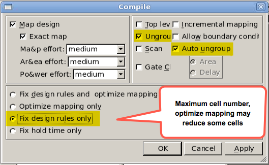
To do that select Design->Compile Design from the menu bar and click OK in the window that pops up.
You can check options Ungroup all and Auto ungroup for best results to flatten your verilog netlist. Then click on Ok
Cell Report
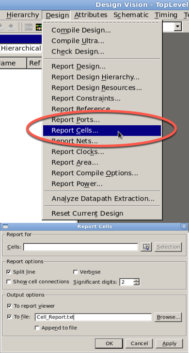
To check your cell number, select Desing -> Report Cells and then OK. You will see the list of cells and total number of them.
Sample Cell Report
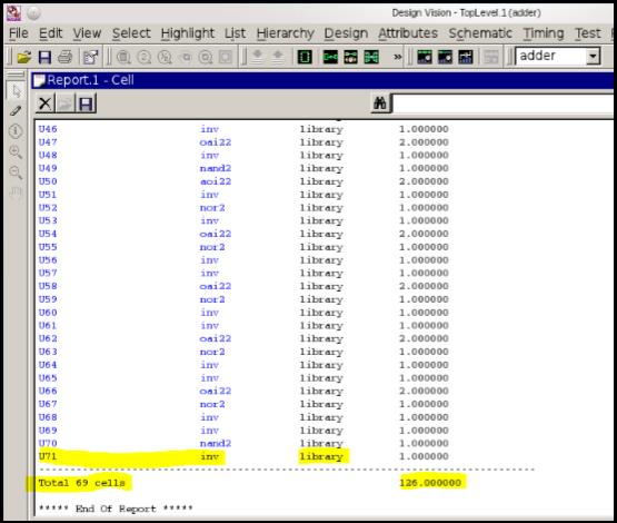
Make sure all the instance are mapped from the library.
If there are some instances like **SEQGEN** or **FFGEN** from the GTECH library then your mapping is incorrect.
Always @ (sginal, ... ) will infer latches and should be avoided !
Since we will design a positive/negative edge triggered Flip flop, and no latch. Your mapped netlist can only use Flip flops, instead of latches. So your code must not infer latches and should be written in a synchronous fashion.
About Group/Ungroup
The group command groups cells (instances) or related components in the design into a new module, creating a new level of hierarchy.
The grouped cells are replaced by a new instance (cell) that references the new module.
Removing a level of hierarchy is called ungrouping. Ungrouping removes (or collapses) the level of hierarchy of the identified subdesign and merges the subdesign with the surrounding logic.
If we choose to ungroup, Design Vision will take all of the logic within the module and combine it with the logic at other levels of the design. This can obtain area benefits by possibly combining redundant logic.
Example:
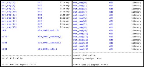
The above picture shows the cell reports from a compile result without checking the ungroup option (left) v.s. the one with ungroup option (right).
The left result has some cells that are not from the library we use, which is not allowed. While the cells in right result are all from our library.
That's why you get more cell count with ungroup.
So my suggestion is: If you compile without ungroup and get the cells required in the project description AND all the cells are from the library, that's fine. Otherwise, compile with ungroup option.
Create Mapped Netlist
To create a verilog (or VHDL) mapped netlist for your design, select File->Save As again.
Specify the filename as your original verilog (or VHDL) file with the addition of _syn.v (i.e.: original: fsm.v ... output: fsm_syn.v) and select verilog (or VHDL) as the file format from the drop-down menu. Click OK.
Now close Synopsys Design Vision by selecting File->Exit.
2. Prepare Mapped Netlist
The resulting verilog (or VHDL) file is a gate-level netlist of your design.
It describes the circuit as a network of devices with names and pins as specified by the Synopsys library.
The netlist is not yet complete, however, as we need to add module descriptions for each of the devices as well.
If you used the Synopsys library file without making any changes, you should be able to use the following file without modification.
Otherwise, you may need to apply changes as you did with the library file.
The following file is a header that can be attached to the verilog (or VHDL) netlist directly, and contains module descriptions for the logic gates that Synopsys constructed the netlist with.
Copy the file to your Synopsys directory by typing:
For Verilog
cp /home/cad/startup/EE6325/aux/header.v .
For VHDL
cp /home/cad/startup/EE6325/aux/header.vhdl .
Adding this to the verilog (or VHDL) mapped netlist, concatenate the two files (header.v first) together or edit the netlist and copy-paste the header into the beginning.
Your mapped verilog (or VHDL) netlist is now ready for verification. You should be able to reattach your test module with minor modifications and verify the functionality of the netlist as compared to the behavioral-level design.
Remember to remove the test module when importing your verilog (or VHDL) netlist into Cadence or Silicon Ensemble later on.
The final file(s) = (header + mapped netlist) + original testbench
NOTICE for VHDL users
- I didn't test VHDL header. If there is an error please let me know. Thanks!
- ENCOUNTER ONLY TAKES VERILOG NETLIST. So to use Encounter, you have to import VHDL file and then select VERILOG type for the output mapped netlist in Design Vision!!
3. Simulate Mapped Netlist
You should be able to simulate your mapped (structural) verilog code using the same testbench circuit used to simulate your behavioral code. You can simulate it with ModelSim,Verilog-XL, etc.
when simulating your mapped code it is necessary to initialize the values of all inputs at time=0.
Compare the simulation waveforms before and after synthesis, they should exactly match.
Kill Design Vision
Again, please quit Design Vision properly by File -> Exit and release occupied license. However, if you have mistakely quit it, you can use following command to kill design_vision process.
pkill -u `id | cut -c 5-10` -f design_vision