HDL - Verilog tutorial
Introduction to Verilog
Here is some infomation related to Verilog
Synthesizable Verilog code
In VLSI design we are mostly concerned with synthesizable verilog. For synthesizing your finite state machine using a tool such as Synopsys Design Compiler, certain rules have to be followed.
Please read those rules carefully; if these rules are not followed, it will cause big problems when using Synopsys
Verilog Restrictions for Synthesis
-
Not all HDL constructs are synthesizable.
-
Simulatable designs are not necessarily synthesizable.
-
Synthesizable constructs are tool dependent
-
Use only few HDL commands
case if else concurrent and sequential statements -
Keep the intended circuit architecture in mind during design description.
-
Using C-like programming style increases the silicon area dramatically.
-
Type conversions and test stimuli definitions cannot be synthesized.
-
Make extensive use of comments.
-
Use headers for all modules, functions
-
Explain the operating modes of the modules
-
Explain all input and output signals
-
Compiler directives reside within comments
-
Smallest HDL code does not imply smallest silicon.
-
Describe the architecture clearly.
-
Cover all possible states within a if-else or case statement.
-
Do not use nested loops for circuit description
-
Do not define functions when instantiating parts within one entity.
Here is some more information about Verilog for synthesis
Synthesizable Verilog Example with Test Bench
Note
The library used in VLSI class only contains flip-flop. In order to only use flip-flop in the design, please only use "posedge clock" in the always block. Put other signals in the block, will cause the synthesizer pick LATCH or other sequential circuits for your design.
Example:
always @ (posedge clock)
begin
    ...
end
Verilog simulator
ModelSim
Windows version
It is already installed in computers of Solarium Lab ECSN 4.324, you can run it without setup.
Linux version
Tip
If you have sourced profile for Cadence tools or Synopsys tools before in the terminal, open a fresh new terminal and start
Go to your cad directory first, if it doesn't exist, use mkdir ~/cad to create one.
cd ~/cad
Source the Mentor profile
. /proj/cad/startup/profile.mentor_2021
To run ModelSim you enter this command
vsim&
Simple simulation steps are as below.
-
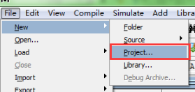
Create new project.
-
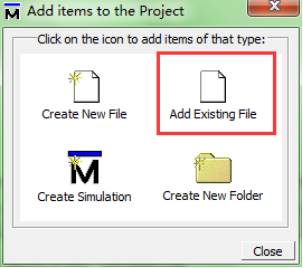
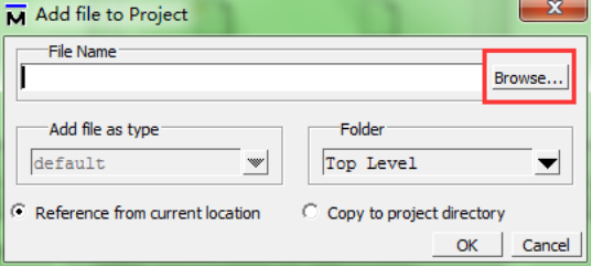
Add source file(s).
-
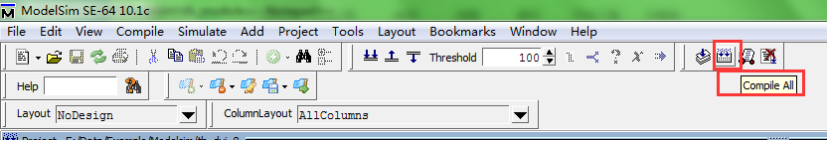
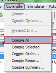
Compile source file(s).
Or:
After compiling successfully:
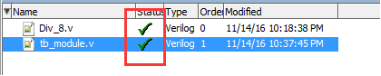
If compilation is unsuccessful, modify the code and compile again.
-
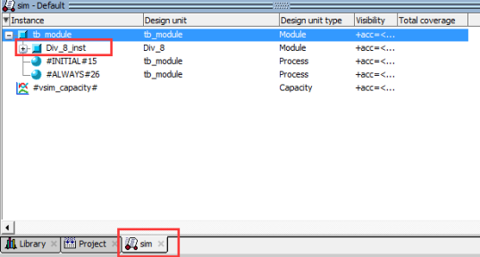
Start simulation, add wave(s).
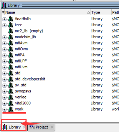
a) Switch to the library tab, click work folder
Right-click the testbench file (as shown below), select the second option
simulation without optimistic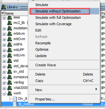
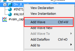
b) Add wave(s)
-
Run simulation and view waveforms.
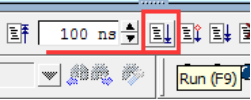
Runis running a fixed time per click (such as 100ns);Run allis running until hit break.Then debug waveforms. If modify source code, you need to re-compile and simulate again.
Here is a detail tutorial, and you can also simulate with VHDL
Please read thought EVERY Section below, if you are not familiar with Verilog.
Verilog syntax and structure
0. Design Entity
In Verilog, a design entity has only one design unit, the module declaration as depicted below.
module Module1
    ...
    `include "module2.v"
    ...
endmodule
Module Declaration: The module declaration is the only design unit (design entity) in Verilog. It describes both a design's interface to other desugns in the same environment, and its functional composition. All declarations used within a model must be declared locally within the module. However, the compiler directive `include is often used to reference to a separate system file. This directive is replaced with the contents of the file it references when compiled by a simulator, synthesizer, or other similar tool. This is very useful for writing generic Verilog code in a separate file that can be referenced from the code in any other Verilog file.
1. Code structure
A design unit may instantiate other design units, which in turn may instantiate other design units in a hierarchial manner. This hierarchical code structure should mimic inferred hardware structure when hardware structure is being modelled. .
Declaration Statements
These statements declare objects for use in concurrent and sequential statements.
In Verilog design unit, a module statement does not need to be declared; nor do subprograms, that is, a task or function. There is mo dedicated declarative region in a module, sequential block, concurrent block, task or function.
Concurrent Statement
These are statements that are executed in paralllel. They operate independently of all other concurrent statements. When modelling hardware strucutre they represent independent sections of the circuit being modeled. Each concurrent statement is executed asynchronously with all other concurrent statement.
The continuous assignment and always statement are concurrent. A continuous assignment uses the reserved word assign to assign data objects of any of the net data types. A task cannot be called concurrently.
Sequential Statements
Sequential statements are statements that are executed depending upon the procedural flow of constructs that surround them.
Sequential statements reside in an always statement. that may, or may not, contain sequential begin-end procedurak blocks. The assigned objects are of type reg or integer.
2. Data Types & Data Objects
Models in Verilog pass data from one point to another using data objects. Each data object has a collection of possible values known as a value set. A data type defines this values set.
Data Types
Verilog defines a single base data type which has the following four values,
0 - represents a logic zero or false condition
1 - represents a logic one or true condition
X - represents an unknown logic value
Z - represents high-impedance state
Data objects of this type are declared in a model to have a single element, or any array of elements. For example,
wire W1;
wire [31:0] W2;
Data Objects
Net and Register data objects. If a net (wire, wand, and wor), or register (reg) data objects are declared withput a range. By default, they are one bit wide and referred to as a scalar. If a range is declared, it has multiple bits and is known as a vector. A vector may be referenced in its entirety, in part, or each individual bit as desired.
Net: represents and models the physical connection of signals. A net object must always be assigned using a continuous assignemtn statement. An assignment assigns values to net and register data types. A continuous assignemtn statement assigns values to any of the net data types and makes a connection to an actual wire in the inferref circuit.
wire:
Models a wire ehich structurally connects two signals together.
wor:
Models a wired OR of several drivers driving the same net. An OR gate will be synthesized.
wand:
Models a wired AND of several drivers driving the same net. An AND gate will be    synthesised.
Register: the register (reg) data object holds its value from one procedural assignment statement to the next and means it holds its value over simulation data cycles. No physical registers will be synthesized. A procedural assignment stores a value in a register data type and is held until the next procedural assignment to that register data type.
reg [3:0] Y1, Y2;
Parameter: a parameter data object defines a constant. Only integer (and not real) parameter constants should be used with synthesis.
parameter A=4'b1011, B=4'b1000;
parameter small=1, medium=2, large=3;
Integer: integer data objects are used to declare general purpose variables for use in loops. They have no direct hardware intent and hold numerical values. No range is specified when an integer object is declared. Integers are signed and produce 2's complement results.
integer N;
3. Operands
An expression comprises of operators and operands. Data objects form the operands of an expression and it is their value that is used by operators in an expression.
3.1 Literals
string (bit & character)
Numeric
real
Character string literals: These are sequences of characters and are useful when designing simulatable test harnesses around a synthesizable model. For example, "ABC".
Numeric Literals: Numeric literals are simple constant numbers that may be specified in binary, octal, decimal or hexadecimal. The specification of its size is optional as Verilog calsulates size based on the longest operand value in an expression, and corresponding assigned value in an assignment. Examples are shown below.
12'b0011_0101_1100 12-bit sized binary constant number
2'O57 2 digit octal number
3_14159 default decimal number
4'h9FDE 4 digit hexadecimal number
module Literals (A1, A2, B1, B2, Y1, Y2);
    input A1, A2, B1, B2;
    output [7:0] Y1;
    output [5:0] Y2;

    parameter CST=4'b1010;
    parameter twentyfive=25; //numeric literal
    reg [7:0] Y1;
    reg [5:0] Y2;

    always @(A or A2 or B1 or B2 or Y1 or Y2)
    begin
    //parenthesis are needed to be syntatically correct
        if (A1==1)
                        Y1={CST,4'b0101}; //bit string literal
        else if (A2==1)
                        Y1={CST,4'b0111}; //bit string literal
        else
                        Y1={CST,4'b1111}; //bit string literal
        if (B==0)
                        Y2=10; //integer literal
        else if (B2==1)
                        Y2=15; //integer literal
        else
                        Y2=twentyfive+10+15; //integer literal end
endmodule
3.2 Identifiers
Module
Parameter
Wire
Register
macros (text substitutions)
An identifier is used to give a name to a data object so that it may be easily referenced in a model. They are the most commonly used type of operand. The value of the named object is returned as the operand value. Verilog is case sensitive, so upper and lower case identifier names are treated as being different identifiers.
module Identifier (A, B, C, D, E, Y1, Y2);
    input A, B, C, D; //identifiers
    input [7:0] E;
    output Y1, Y2;
    reg F, Y1, Y2; //identifiers

    function AND_OR_Bits;
        input [7:0] A;
        begin
                        AND_OR_Bits=(A[7] & A[6] & A[5] & A[4]) & (A[3] | A[2] | A[1] | A[0]);
        end
    endfunction

    always @(A or B or C or D or E)
    begin
        F=A&B&AND_OR_Bits(E);
        Y1=C&F;
        Y2=D|F;
    end
endmodule
3.3 Function calls
Function calls, which must reside in an expression, are operands. The single value returned from a function is the operand value used in the expression.
module Functional_Calls (A1, A2, A3, A4, B1, B2, Y1, Y2);
    input A1, A2, A3, A4, B1, B2;
    output Y1, Y2;
    reg Y1, Y2;

    function function1;
        input F1, F2, F3, F4;
        begin
                        function1=(F1 & F2) | (F3 & F4);
        end
    endfunction

    always @(A1 or A2 or A3 or A4 or B1 or B2)
    begin
        Y1=function1(A1,A2,A3,A4)|B1|B2;
        Y2=B1||B2||function1(A1,A2,A3,A4);
    end
endmodule
3.4 Index and Slice Name
An index named operand specifies a single element of an array. For synthesis the array may be of type constant, variable, or signal. A slice named operand is a sequence of elements within an arraty and is identified Verilog using the colon ":".
module Index_Slice_Name (A, B, Y);
    input [5:0] A, B;
    output [11:0] Y;
    parameter C=3'b100; reg [11:0] Y;

    always @(A or B)
    begin
        Y[2:0]=A[0:2]; //swap bits
        Y[3]=A[3]&B[3]; //single index
        Y[5:4]={A[5]&B[5],A[4]|B[4]};
        Y[8:6]=B[2:0]; //3-bit slice
        Y[11:9]=C;
    end
endmodule
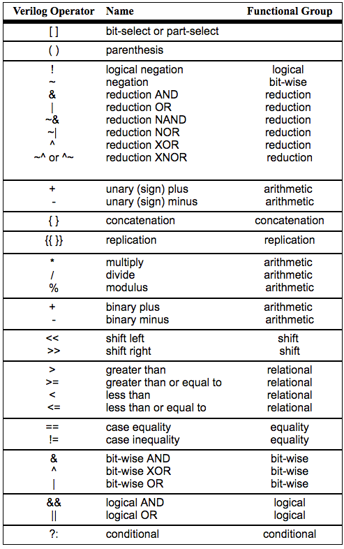
4. Operators
Operators perform an opeation on one or more operands within an expression. An expression combines operands with appropriate operators to produce the desired functional expression.
Groups of Verilog operators are shown on the left. The table shows the operators in descending order of precedence. Operators with equal precedence are shown grouped.
4.1 Arithmetic
There are five arithmetic operators in Verilog.
module Arithmetic (A, B, Y1, Y2, Y3, Y4, Y5);
    input [2:0] A, B;
    output [3:0] Y1;
    output [4:0] Y3;
    output [2:0] Y2, Y4, Y5;
    reg [3:0] Y1;
    reg [4:0] Y3;
    reg [2:0] Y2, Y4, Y5;

    always @(A or B)
    begin
        Y1=A+B;//addition
        Y2=A-B;//subtraction
        Y3=A*B;//multiplication
        Y4=A/B;//division
        Y5=A%B;//modulus of A divided by B
    end
endmodule
4.2 Sign
These operators simply assign a positive "+" or negative "-" sign to a singular operand. Usually no sign operators is defined, in which case the default "+" is assumed.
module Sign (A, B, Y1, Y2, Y3);
    input [2:0] A, B;
    output [3:0] Y1, Y2, Y3;
    reg [3:0] Y1, Y2, Y3;

    always @(A or B)
    begin
        Y1=+A/-B;
        Y2=-A+-B;
        Y3=A*-B;
    end
endmodule
4.3 Relational
Relational operators compare two operands and returns an indication of whether the compared relationship is true or false. The result of a comparison is either 0 or 1. It is 0 if the comparison is false and 1 is the comparison is true.
module Relational (A, B, Y1, Y2, Y3, Y4);
    input [2:0] A, B;
    output Y1, Y2, Y3, Y4;
    reg Y1, Y2, Y3, Y4;

    always @(A or B)
    begin
        Y1=A<B;//less than
        Y2=A<=B;//less than or equal to
        Y3=A>B;//greater than
        if (A>B)
                        Y4=1;
        else
                        Y4=0;
    end
endmodule
4.4 Equality and inequality
Equality and inequality operators are used in exactly the same way as relational operators and return a true or false indication depending on whether any two operands are equivalent or not.
module Equality (A, B, Y1, Y2, Y3);
    input [2:0] A, B;
    output Y1, Y2;
    output [2:0] Y3;
    reg Y1, Y2;
    reg [2:0] Y3;
    always @(A or B)
    begin
        Y1=A==B;//Y1=1 if A equivalent to B
        Y2=A!=B;//Y2=1 if A not equivalent to B
        if (A==B)//parenthesis needed
            Y3=A;
        else
            Y3=B;
    end
endmodule
4.5 Logical
Logical comparison operators are used in conjuction with relational and equality operators as described in the relational operators section and equality and inequality operators section. They provide a means to perform multiple comparisons within a a single expression.
module Logical (A, B, C, D, E, F, Y);
    input [2:0] A, B, C, D, E, F;
    output Y;
    reg Y;

    always @(A or B or C or D or E or F)
    begin
        if ((A==B) && ((C>D) || !(E<F)))
            Y=1;
        else
            Y=0;
    end
endmodule
4.6 Bit-wise
Logical bit-wise operators take two single or multiple operands on either side of the operator and return a single bit result. The only exception is the NOT operator, which negates the single operand that follows. Verilog does not have the equivalent of NAND or NOR operator, their funstion is implemented by negating the AND and OR operators.
module Bitwise (A, B, Y);
    input [6:0] A;
    input [5:0] B;
    output [6:0] Y;
    reg [6:0] Y;

    always @(A or B)
    begin
        Y(0)=A(0)&B(0); //binary AND
        Y(1)=A(1)|B(1); //binary OR
        Y(2)=!(A(2)&B(2)); //negated AND
        Y(3)=!(A(3)|B(3)); //negated OR
        Y(4)=A(4)^B(4); //binary XOR
        Y(5)=A(5)~^B(5); //binary XNOR
        Y(6)=!A(6); //unary negation
    end
endmodule
4.7 Shift
Shift operators require two operands. The operand before the operator contains data to be shifted and the operand after the operator contains the number of single bit shift operations to be performed. 0 is being used to fill the blank positions.
module Shift (A, Y1, Y2);
    input [7:0] A;
    output [7:0] Y1, Y2;
    parameter B=3; reg [7:0] Y1, Y2;

    always @(A)
    begin
        Y1=A<<B; //logical shift left
        Y2=A>>B; //logical shift right
    end
endmodule
4.8 Concatenation and Replication
The concatenation operator "{ , }" combines (concatenates) the bits of two or more data objects. The objects may be scalar (single bit) or vectored (muliple bit). Mutiple concatenations may be performed with a constant prefix and is known as replication.
module Concatenation (A, B, Y);
    input [2:0] A, B;
    output [14:0] Y;
    parameter C=3'b011;
    reg [14:0] Y;

    always @(A or B)
    begin
        Y={A, B, (2{C}}, 3'b110};
    end
endmodule
4.9 Reduction
Verilog has six reduction operators, these operators accept a single vectored (multiple bit) operand, performs the appropriate bit-wise reduction on all bits of the operand, and returns a single bit result. For example, the four bits of A are ANDed together to produce Y1.
module Reduction (A, Y1, Y2, Y3, Y4, Y5, Y6);
    input [3:0] A;
    output Y1, Y2, Y3, Y4, Y5, Y6;
    reg Y1, Y2, Y3, Y4, Y5, Y6;

    always @(A)
    begin
        Y1=&A; //reduction AND
        Y2=|A; //reduction OR
        Y3=~&A; //reduction NAND
        Y4=~|A; //reduction NOR
        Y5=^A; //reduction XOR
        Y6=~^A; //reduction XNOR
    end
endmodule
4.10 Conditional
An expression using conditional operator evaluates the logical expression before the "?". If the expression is true then the expression before the colon (:) is evaluated and assigned to the output. If the logical expression is false then the expression after the colon is evaluated and assigned to the output.
module Conditional (Time, Y);
    input [2:0] Time;
    output [2:0] Y;
    reg [2:0] Y;
    parameter Zero =3b'000;
    parameter TimeOut = 3b'110;

    always @(Time)
    begin
        Y=(Time!=TimeOut) ? Time +1 : Zero;
    end
endmodule